
Choosing a carbon fiber to carbon fiber adhesive sounds straightforward until a promising joint fails at the edge, lifts under cyclic load, or loses performance after heat and moisture exposure. CFRP-to-CFRP bonding is rarely limited by published shear strength alone. In real structures, engineers must manage laminate stiffness, load direction, surface condition, bond-line control, and joint geometry together. A strong bonded joint is usually the result of balanced design decisions rather than a single “strong” adhesive grade.
If your project involves shells, panels, tubes, sporting structures, mobility components, enclosures, or lightweight industrial assemblies, our carbon fiber adhesive manufacturing support for structural joints is built around the issues that typically decide field reliability: adhesive toughness, controlled viscosity, bond-line stability, cure profile, substrate-specific surface preparation, and production-ready packaging. We help customers evaluate samples, adjust formulations where needed, and plan for repeatable OEM or bulk manufacturing rather than one-off lab success.
From our adhesive manufacturing perspective, the biggest mistake in CFRP bonding is treating the joint like a metal lap shear coupon and assuming the highest listed strength will translate into the safest assembly. Carbon fiber laminates are anisotropic, edges are vulnerable, and thin rigid bond lines can concentrate stress quickly. That is why adhesive selection, joint design, and process control need to be discussed together from the beginning.
Why carbon fiber-to-carbon fiber bonding requires more than high shear strength
Many buyers begin with a data sheet and look for a high shear number. That is understandable, but CFRP joints often fail because the joint is exposed to peel, cleavage, or dynamic loading that the simple headline value does not represent well. A bonded carbon fiber structure may experience bending, impact, torsion, vibration, thermal cycling, or assembly misalignment. Any of these can create local stress concentrations that exceed what a brittle or overly stiff adhesive can tolerate.
For CFRP-to-CFRP assemblies, we usually advise teams to examine at least five things together: laminate construction, expected load path, service temperature, bond-line thickness target, and production method. A part bonded in a static panel assembly may accept a different adhesive profile than a tube joint exposed to road shock or repeated flexing. In practice, a slightly lower shear value with much better toughness can produce a more reliable structure.
When buyers compare epoxy adhesive options for high-strength composite bonding, we encourage them to ask not only how strong the adhesive is, but how the cured network handles crack propagation, edge stresses, and long-term durability. That framing usually leads to better decisions than comparing one test number in isolation.
How load transfer works in composite laminates and why the substrate matters
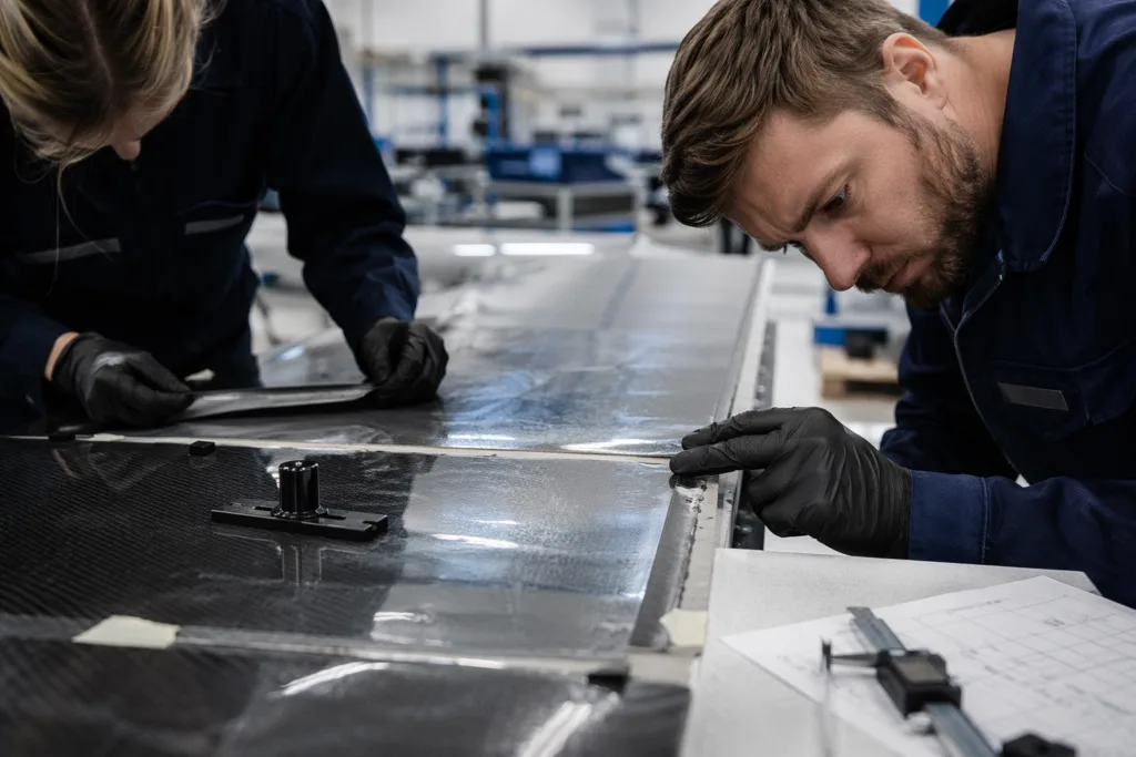
Carbon fiber reinforced polymer is not a uniform material. The fibers carry load efficiently in preferred directions, while the resin matrix supports the fibers, transfers stress between plies, and influences interlaminar behavior. When two CFRP parts are bonded, the adhesive does not operate independently from the laminate. The bonded region becomes a system involving the outer resin-rich surface, any exposed fibers, the ply orientation beneath the surface, and the adhesive layer itself.
Load transfer in a bonded lap joint is usually highest near the ends of the overlap. If the adherends are thin or if bending is introduced, the edge of the joint can see elevated peel stress even when the average shear looks modest. This is one reason overlap length does not always improve performance in a simple linear way. Composite joint design guidance, including NASA guidance on bonded composite joint design and peel-stress control, consistently points engineers back to geometry and stress distribution rather than strength numbers alone.
The substrate also matters because CFRP surface quality varies widely. A glossy molded surface may still carry mold release residue. A sanded panel may expose fiber at one area and remain resin-rich in another. A co-cured part and a post-cured part can present different bonding behavior. In our development work, we often see variability caused less by adhesive chemistry and more by inconsistent laminate surface state before bonding.
Peel, cleavage, and edge-lift risks in bonded carbon fiber joints
Peel failure is one of the most common reasons structural composite joints underperform outside the lab. In a peel-dominated event, the adhesive is forced to resist a lifting force at the edge of the bond line, often over a very small area. Cleavage loading is similar in that stress becomes highly concentrated at one end or line of the joint. Because composites can be stiff and thin, even small deflection can amplify this effect.
Typical sources of peel and edge-lift risk include:
- Single-lap joints that create eccentric loading and joint rotation
- Thin adherends that bend under load
- Sharp overlap ends with no taper or reinforcement
- Overly rigid adhesives with poor crack-stopping behavior
- Very thin bond lines that cannot absorb differential strain
- Thermal expansion mismatch between bonded subcomponents
- Impact or repeated dynamic loading in service
In practical design reviews, we spend a lot of time asking where the first crack is likely to start. It is often not in the middle of the overlap. It is at the edge, corner, or transition region. That is why understanding why peel resistance matters in epoxy joint design is so important when choosing an adhesive for CFRP structures that will see bending or fatigue.
Adhesive properties that matter most
For CFRP-to-CFRP bonding, the most important adhesive properties are usually not a single maximum strength figure but a package of mechanical and processing behavior. We generally focus on toughness, elongation, modulus, fatigue resistance, thermal stability, and viscosity control.
Toughness
A tough adhesive can absorb energy and slow crack growth. This matters in carbon fiber assemblies because a joint may be locally overloaded during impact, transport, fastener installation near the bond area, or repeated vibration. Toughened epoxies and certain structural acrylic systems are often considered when crack resistance is critical.
Elongation
Some elongation helps the adhesive redistribute stress instead of failing abruptly at a concentrated point. Too little elongation can make the joint brittle. Too much can reduce rigidity or dimensional control, depending on the application. The right balance depends on whether the structure values stiffness, impact tolerance, or strain accommodation more heavily.
Modulus
A higher modulus adhesive can transfer load efficiently, but if it is too rigid for the joint design, it may intensify peel and edge stresses. Lower modulus systems can reduce peak stress, but they may also allow more movement. The best choice depends on joint geometry and service loading, not a universal rule.
Fatigue resistance
Many CFRP structures fail in the field because of repeated moderate loads rather than one high load. Fatigue resistance should be considered early for panels, frames, drones, mobility parts, machine covers, and rotating or vibrating assemblies.
Environmental durability
Heat, humidity, water ingress, oils, and cleaning chemicals can all shift joint performance over time. Some adhesives maintain stiffness well at elevated temperature but become less tolerant of impact. Others remain tougher in variable environments but require longer curing or stricter surface preparation.
Viscosity and gap-filling behavior
Composite parts are not always dimensionally perfect. If the bond line has local gaps, waviness, or curvature, the adhesive must flow enough to wet the surface but not slump excessively. Gap-filling behavior strongly affects bond-line quality and final strength consistency.
In some assemblies, a structural acrylic such as ZDS-8100AB acrylic structural adhesive for demanding bonded assemblies may be worth evaluating where process speed, surface tolerance, or balanced toughness is important. In other cases, a toughened epoxy remains the better fit for heat resistance, stiffness, or long-term structural stability. The right answer comes from the joint, not the category name.
Bond-line thickness: why too thin or too thick can weaken a CFRP joint
Bond-line thickness is often underestimated in composite bonding. If the bond line is too thin, the adhesive may not fully wet the surface topography, may trap dry spots, and may become too rigid to absorb stress concentrations. If it is too thick, the joint may lose stiffness, cure less evenly, or develop greater shrinkage and internal stress.
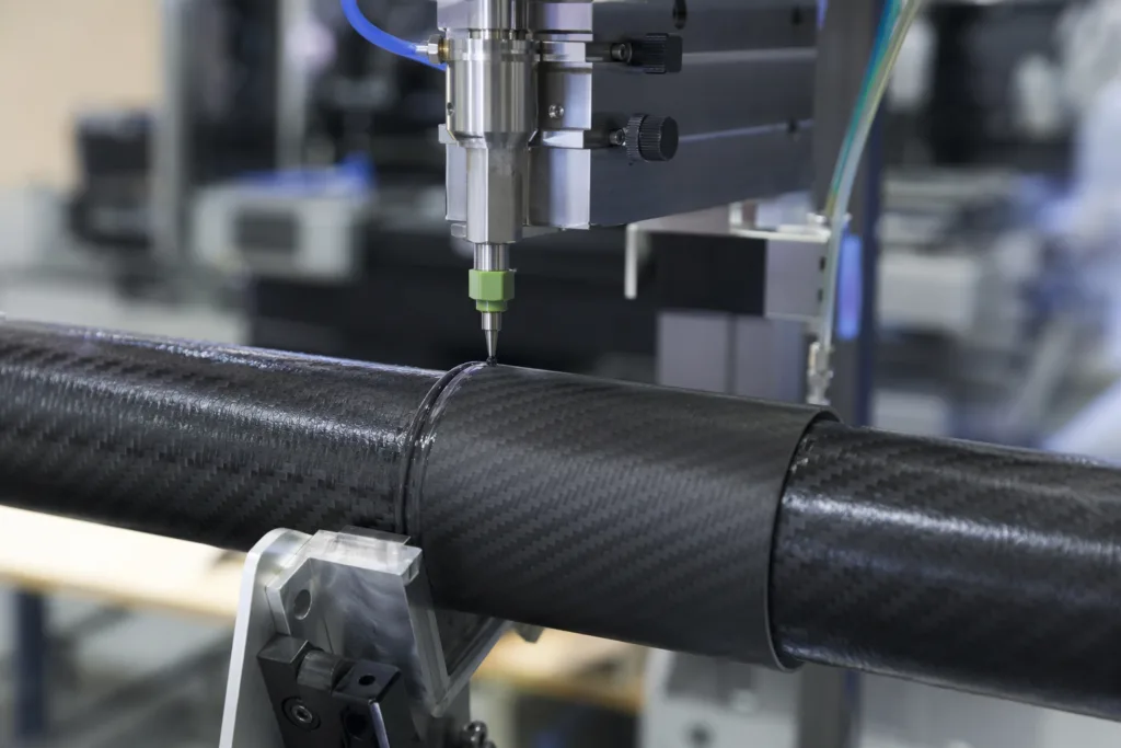
For CFRP bonding, the practical goal is a controlled and repeatable bond line that matches adhesive rheology and structural demand. Thin precision-fit parts may benefit from lower-viscosity adhesives with spacers or glass beads for thickness control. Parts with molded variation may need a thixotropic system that bridges gaps without running.
Warning signs of poor bond-line control include:
- Adhesive starvation at the overlap edge
- Excess squeeze-out and dry center areas
- Large thickness variation across the same part
- Void formation from poor wetting or trapped air
- Unstable fixture alignment during cure
At ZDS, when a customer is moving from prototypes to volume production, bond-line thickness control is often one of the first process variables we revisit. It affects not only strength, but also cycle time, adhesive consumption, and assembly repeatability.
Joint geometry choices for stronger CFRP bonding
Good adhesive chemistry cannot fully rescue poor geometry. Joint design is one of the most powerful ways to reduce peel stress and improve CFRP bond reliability.
Lap joints
Single-lap joints are common because they are easy to manufacture, but they create eccentric loading that can rotate the joint and raise peel stress at the ends. They are useful for evaluation and many practical assemblies, but should be designed carefully when structural loads are meaningful.
Scarf joints
Scarf joints spread load over a longer, more gradual interface and can reduce abrupt stress concentration. They are often preferred where load transfer efficiency and aerodynamic or dimensional smoothness matter, although machining and preparation can be more demanding.
Tapered joints
Tapering the adherend or overlap transition helps reduce edge effects. Even a relatively simple design change at the overlap end can improve stress distribution.
Stepped and reinforced joints
Where high loads or fatigue are expected, designers may use stepped features, secondary reinforcement plies, or hybrid bonding concepts that combine adhesive with mechanical retention. These approaches can improve damage tolerance, though they also increase process complexity.
As a general rule, if a joint must carry meaningful structural load in a lightweight assembly, the geometry should be reviewed as seriously as the adhesive itself. This is where adhesive selection technical support for composite joint design becomes valuable, because the right recommendation depends on the interaction between part shape, cure process, and service environment.
| Joint Type | Main Advantage | Main Risk | Typical Use Logic |
|---|---|---|---|
| Single lap | Simple fabrication | Peel from joint rotation | Use when manufacturing simplicity is important and load is moderate |
| Double lap | Better load symmetry | More assembly steps | Use when reducing eccentric loading is a priority |
| Scarf | Smooth load transfer | Surface prep and machining complexity | Use for high-performance lightweight structures |
| Tapered overlap | Lower edge stress | Design and tooling effort | Use to reduce crack initiation at overlap ends |
| Reinforced bonded joint | Improved damage tolerance | Higher cost and process complexity | Use in fatigue-sensitive or safety-critical assemblies |
Surface preparation for carbon fiber parts
Surface preparation is often the line between repeatable structural bonding and unpredictable failures. CFRP parts can carry mold release, sanding dust, oils, fingerprints, or weak boundary layers. A visually clean part is not necessarily bond-ready.
For most projects, a robust surface preparation sequence includes:
- Process review to identify release agents, post-cure condition, and handling contamination risk
- Cleaning with a suitable solvent or approved cleaner compatible with the composite resin system
- Controlled abrasion when appropriate to remove weak surface layers and increase mechanical keying
- Thorough dust removal after abrasion
- Limited handling before bonding to prevent recontamination
- Primer use when supported by the adhesive system and process validation
We recommend avoiding over-aggressive abrasion that damages fibers or creates an inconsistent surface profile. The goal is surface activation and contaminant removal, not uncontrolled laminate damage. In production, the exact abrasive grade, wipe method, drying time, and maximum open window after preparation should all be documented. This is one of the most common areas where good prototype results fail to scale.
Selecting the right structural adhesive for CFRP-to-CFRP bonding
There is no single universal carbon fiber to carbon fiber adhesive. The right selection depends on what the joint must do, how the parts are made, and how the assembly line operates.
| Selection Factor | What to Ask | Why It Matters |
|---|---|---|
| Load type | Is the joint mainly in shear, peel, impact, or fatigue? | Determines toughness and modulus balance |
| Service temperature | Will the bonded part see heat spikes or outdoor cycling? | Affects glass transition needs and durability |
| Part fit-up | Are gaps tight and controlled or variable? | Drives viscosity and gap-filling choice |
| Assembly speed | How much open time and fixture time are available? | Controls workability and throughput |
| Surface condition | Are parts co-cured, post-cured, glossy, abraded, or primed? | Impacts wetting and adhesion consistency |
| Final property target | Is stiffness or damage tolerance more important? | Shapes chemistry and formulation direction |
In broad terms, toughened epoxies are often chosen for structural composite bonding because they combine high cohesive strength with good environmental resistance and tunable toughness. Structural acrylics can be attractive when faster fixture, more forgiving surface interaction, or specific processing advantages are needed. Polyurethanes may also be useful where flexibility and stress absorption are important, though they are not always the first choice for rigid high-temperature CFRP structures.
For buyers evaluating a supplier, it helps to ask whether standard products can be modified for viscosity, cure speed, thixotropy, color, packaging, or toughness. A manufacturer-centered conversation is usually more useful than a catalogue-only comparison. In many projects, ZDS works with customers first through sample selection, then through process trials, and finally through any formulation adjustment needed for their real production conditions.
Applications in shells, tubes, panels, frames, and lightweight structures
Different CFRP formats create different adhesive requirements. A flat panel bond may prioritize dimensional accuracy and broad-area shear transfer. A tube-to-socket joint may need gap filling and better crack resistance at the overlap edge. A shell or housing may require impact tolerance and cosmetic squeeze-out control. A frame subassembly may need a balance of stiffness and fatigue life.
Examples of application-specific considerations include:
- Panels and skins: broad-area wetting, low void content, controlled thickness, thermal cycling durability
- Tubes and sleeves: circumferential fit variation, torsional loading, edge reinforcement, controlled dispensing
- Frames and brackets: mixed bending and vibration, local stress risers, fixture speed
- Composite housings: appearance, edge sealing, impact tolerance, room-temperature assembly
- Hybrid subassemblies: CFRP-to-CFRP sections bonded near inserts, fasteners, or dissimilar materials
These differences are why we recommend testing candidate adhesives on realistic substrates and representative geometry whenever possible, not only on generic coupons.
Common CFRP joint failure modes and how to prevent them
Understanding failure mode is essential. If the joint fails, the visible break pattern often tells you whether the problem came from chemistry, process, or design.
Adhesive failure at the interface
This often points to contamination, weak surface preparation, incompatible surface chemistry, or insufficient wetting. Review cleaning, abrasion, and the time between preparation and bonding.
Cohesive failure within the adhesive
This can indicate the adhesive is the weak link under the given load or environmental condition, but it can also reflect incomplete cure, incorrect mix ratio, or unsuitable bond-line thickness.
Substrate failure or delamination
If the CFRP itself fails first, the adhesive may actually be stronger than the laminate surface region. This can be acceptable or even desirable in some structural contexts, but it still requires analysis of ply design and local laminate reinforcement.
Edge cracking and progressive peel growth
This is common in joints with bending, cyclic loading, or overly stiff brittle bond lines. Geometry changes, thickness control, and a tougher adhesive often help.
Environmental degradation
Heat, moisture, and fluid exposure can soften or embrittle the system over time. Validation should include aged samples, not only freshly cured parts.
Teams troubleshooting bond issues often benefit from reviewing common causes of adhesive bond failure, especially when prototype joints performed well but production units began failing inconsistently.
Testing and validation for safer design decisions
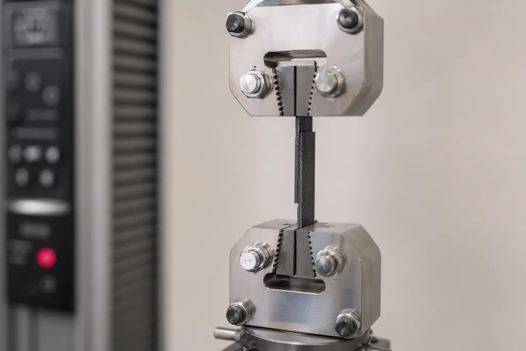
Testing should be used to compare candidate adhesives, verify process robustness, and expose failure modes before scale-up. For CFRP joints, shear testing is useful, but it should not be the only gate. A recognized reference for composite lap shear evaluation is ASTM D5868 lap-shear testing for FRP composite bonds, which is particularly relevant when comparing adhesives on fiber-reinforced substrates rather than assuming metal-bond data is transferable.
Single-lap coupon testing can also be useful for in-process comparison, though engineers should remember that coupon geometry can exaggerate or hide certain stress effects depending on the setup. More important than one pass result is a test plan that includes the real variables your product will face.
A practical validation plan often includes:
- Lap shear comparison on actual or equivalent CFRP substrates
- Peel-sensitive or edge-loaded evaluation where relevant
- Fatigue cycling under realistic stress levels
- Environmental aging with heat and humidity exposure
- Bond-line thickness variation study
- Surface preparation robustness checks
- Mix-ratio, cure, and fixture-window process limits
- Production QC checks for every batch or shift as needed
From a manufacturing standpoint, we also advise customers to decide early what “pass” means. Is the goal highest initial strength, or minimum strength after aging? Is visual bond-line quality critical? Is the adhesive being selected for hand assembly, meter-mix dispensing, or automated bead application? These decisions influence both qualification and sourcing.
When custom formulation is needed
Standard products are often enough, but not always. Custom formulation becomes valuable when the project needs a property combination that is difficult to achieve with an off-the-shelf adhesive. Common reasons include faster fixture without losing toughness, higher service temperature, reduced exotherm in large bond volumes, better non-sag behavior on vertical joints, lower odor, color matching, or improved dispensing through a specific ratio system.
We also see custom work requested when customers need better crack resistance in edge-loaded joints, more forgiving cure in cooler factory conditions, or packaging formats matched to their assembly cell. For procurement teams, this matters because the adhesive is no longer only a material choice; it becomes part of production planning, waste control, and quality consistency. In such cases, a structured development path with formulation review, samples, pilot runs, and scale-up checkpoints is more reliable than switching products repeatedly during production pressure.
How we help customers build more reliable carbon fiber joints
Our role as a manufacturer is not just to supply adhesive, but to align chemistry with joint behavior and plant realities. We usually begin by reviewing the substrate, part geometry, load case, target cure speed, service environment, and dispensing method. That allows us to narrow whether a toughened epoxy, structural acrylic, or another system makes sense for the application.
We then support sample evaluation with guidance on surface preparation, bond-line thickness, cure schedule, and what failure patterns to watch during trials. If the standard grade is close but not ideal, we can discuss whether viscosity, thixotropy, working time, or toughness should be adjusted. For OEM and private label customers, packaging format, batch consistency, shelf life planning, and production documentation are just as important as peak lab strength.
The most successful CFRP bonding projects are usually the ones that treat adhesive, design, and process as one engineering system. That approach reduces surprises during scale-up and lowers the risk of peel-driven failures later in service.
Key takeaways for sourcing, prototyping, and scale-up
A carbon fiber to carbon fiber adhesive should be selected around the joint’s real stress state, not just a published strength number. Peel and edge-lift risks often determine whether a bonded CFRP assembly survives in service. Toughness, modulus balance, bond-line thickness control, and surface preparation discipline are usually the decisive variables.
For buyers and engineers, the safest path is to combine design review, representative testing, and process planning early. Ask how the adhesive behaves under fatigue, after aging, and at realistic thickness. Ask whether the supplier can support formulation adjustment, technical troubleshooting, and production consistency. Those questions usually matter more than chasing the highest headline result.
When CFRP structures are designed with better load transfer, controlled edges, clean surfaces, and the right adhesive profile, bonded joints can become lighter, cleaner, and more durable without creating avoidable peel failure.
FAQs
What is the best adhesive type for bonding carbon fiber to carbon fiber?
The best choice depends on the joint design and service conditions rather than one universal chemistry. Toughened epoxies are often preferred for structural CFRP bonding because they balance strength, stiffness, and environmental durability, while structural acrylics may be useful when faster fixture, surface tolerance, or different toughness behavior is needed. The right selection should consider peel risk, bond-line thickness, temperature exposure, and production method.
Why do carbon fiber bonded joints fail at the edges first?
Edge failure usually happens because stress is not distributed evenly through the overlap. Single-lap geometry, bending, thin adherends, and overly rigid bond lines can create peel or cleavage stress at the overlap ends. Once a crack starts at the edge, it can grow progressively under vibration, impact, or fatigue, so joint geometry and adhesive toughness are critical to prevention.
How should carbon fiber surfaces be prepared before adhesive bonding?
Most CFRP parts need cleaning to remove release agents, oils, and handling contamination, followed by controlled abrasion when appropriate and careful dust removal before bonding. The exact process depends on the laminate and resin system, but consistency is essential. Over-abrasion can damage the surface, while under-preparation can leave a weak boundary layer that causes interface failure.
Is a thinner bond line always stronger for CFRP bonding?
No. A bond line that is too thin can lead to adhesive starvation, poor wetting, and higher local stress concentration, especially in peel-sensitive joints. A bond line that is too thick can reduce stiffness, create cure variation, or increase void risk. The goal is a controlled thickness that suits the adhesive rheology, part fit-up, and structural load path.
What testing should buyers request before approving a CFRP adhesive?
Buyers should ask for testing that reflects actual use conditions, including lap shear on representative CFRP substrates, environmental aging, and fatigue or peel-sensitive evaluation when the design requires it. It is also helpful to review bond-line thickness effects, surface preparation sensitivity, and cure-window limits. A useful approval plan looks beyond one fresh coupon result and checks whether the process is robust in production.
When is custom formulation worth considering for carbon fiber bonding?
Custom formulation is worth considering when a standard adhesive is close but does not fully match the process or performance target. Typical reasons include needing faster fixture time, better sag resistance, more toughness against peel, higher temperature resistance, a different viscosity for dispensing, or packaging suited to the assembly line. For volume production, a tailored formula can improve consistency and reduce process compromise.